Thursday, July 19, 2012

NORMAL MODES ANALYSIS


       The Modal Analysis (Normal Mode Analysis; SOL 103) of a Rectangular Plate

  • While performing Modal Analysis Make sure you define Material>Density
  • And if you want to analyse for a particular frequency Go for "Frequency Response"
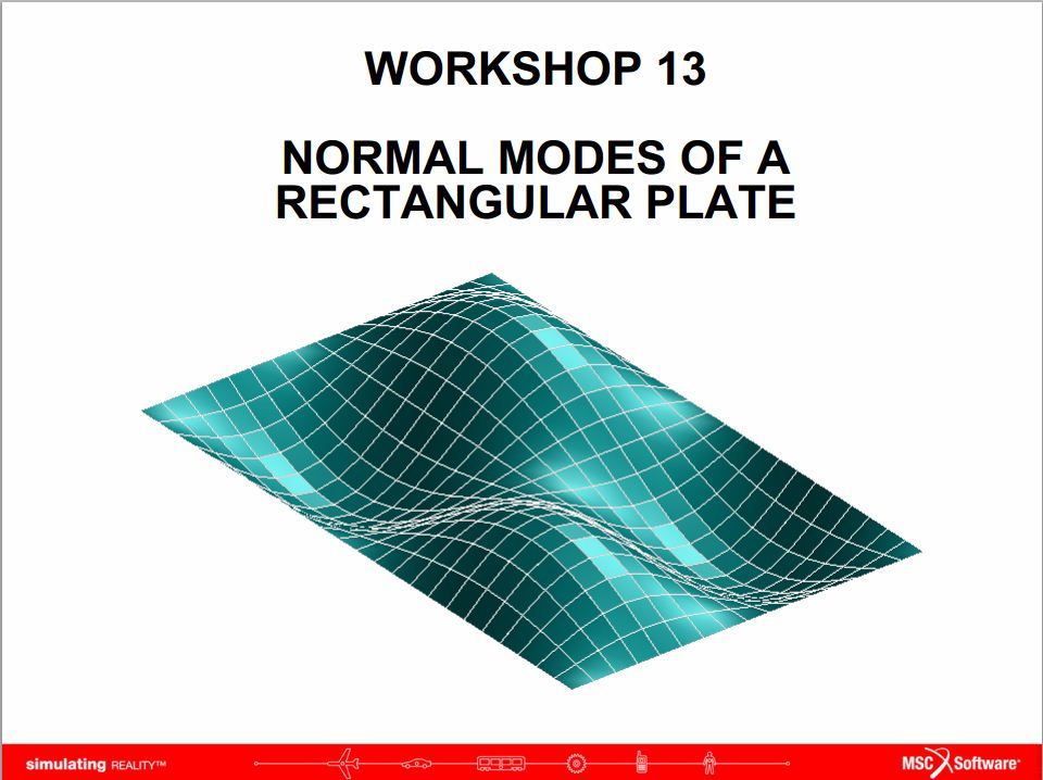


       Wiki Says > A normal mode of an oscillating system is a pattern of motion in which all parts of the system move sinusoidally with the same frequency and with a fixed phase relation. The motion described by the normal modes is called resonance. The frequencies of the normal modes of a system are known as its natural frequencies or resonant frequencies. A physical object, such as a building, bridge or molecule, has a set of normal modes that depend on its structure, materials and boundary conditions.
       When relating to music, normal modes of vibrating instruments (strings, air pipes, drums, etc.) are called "harmonics" or "overtones".
       The most general motion of a system is a superposition of its normal modes. The modes are normal in the sense that they can move independently, that is to say that an excitation of one mode will never cause motion of a different mode.
       The concept of normal modes also finds application in wave theory, optics, quantum mechanics, and molecular dynamics.
       A mode of vibration is characterized by a modal frequency and a mode shape, and is numbered according to the number of half waves in the vibration. For example, if a vibrating beam with both ends pinned displayed a mode shape of half of a sine wave (one peak on the vibrating beam) it would be vibrating in mode 1. If it had a full sine wave (one peak and one valley) it would be vibrating in mode 2.

..........................................

VERIFYING THE MESH QUALITY


        Now try verifying the mesh quality of the of an object using simple TET mesh.

  • You will notice that varying the Mesh size varies the ELEMENT QUALITY.
  • If u run a analysis you would also find that the result value keep changing for diff element size.This is due to convergence of the result value


................................


CREATING SOLID FROM SURFACE (.iges > solid)


       During my preliminary days of work i had this great difficulty to tackle the conversion of .iges file (Initial Graphics Exchange Specification) to Solid , because i use to work much with .model file in my training days.       until i got much familiar with the B-rep option.

       GEOMETRY:: CREATE>SOLID>B-REP


.......................

WHAT, WHO, WHEN


MSC Nastran and Patran is a finite element analysis (FEA) program that was originally developed for NASA in the late 1960s under United States government funding for the Aerospace industry. The MacNeal-Schwendler Corporation (MSC) was one of the principal and original developers of the public domain NASTRAN code. NASTRAN source code is integrated in a number of different software packages, which are distributed by a range of companies.

(courtesy: Wikipedia)


Wednesday, July 18, 2012

Haii


       The blog is meant to HELP beginners, student and advanced users to tackle daily issues and problem faced while using MSC Nastran & Patran.

       Soon I will attach reliable links and file to simplify your working with MSC Nastran & Patran.


       Stephin